
This post refers to the tool I recently released and have been working on here: https://github.com/7ark/CSGO-VMF-Generator.
This is a tool made for CS:GO that allows you to create VMF files for levels and otherwise, including entering black and white images and creating levels out of them. In this post I will go over broadly the work that went into this, algorithms and challenges, and challenges I’ve still yet to fix.
Initial Setup
So for the beginning of this project I started with simply attempting to create a VMF file. For those who aren’t familiar, VMF’s are what you use in Hammer (CS:GO/Sources level creator essentially) to make and compile levels. Luckily these are in plain text, which makes it very easy to read and emulate their formatting. Unfortunately their formatting sucks. There is a page that broadly goes over the formatting here: https://developer.valvesoftware.com/wiki/Valve_Map_Format
So at the beginning I simply started setting up some rudimentary text generation matching the style of the VMF. I simply created constants for some of the stuff that didn’t need to change, such as the beginning headers noting versions and grid size. Once that was done I setup a format to begin entering various shapes into text data without having the data for it yet as a placeholder. This was all very simple and was just adding lines to text to match formats, nothing really exciting happened here. Next we get into creating actual shapes.
Shapes and Such
Next I created a new class to represent our basic shape. Believe it or not, this was simply called Shape. It’s a simple abstract class holding some basic data. This includes things such as position, information about sides (to be used later in the text for the VMF) and a generic ShapeData class that could be overwritten as well. I did this in another class so I could simply pass this in when I created the shape without having to fill out every piece of data. Originally this was passed in via a function where this mattered, later I removed that, but it still remains to this day. Oh well.
Then I created a virtual GenerateSides function, which is where the pain began. So as a quick explanation, VMFs are formatted in such a way that it defines a solid, and within that solid it stores several sides, which then define a plane made up of 3 Vector3s to represent a triangle. Now you might ask, what about the fourth point to make a square? Or what if the shape you’re making has more than 4 sides? And the answer is, I have absolutely no idea. You fill it in and it just sort of seems to… fix itself. I honestly have no idea the exact calculations to make this perfect to this day, but as long as you get it pretty much correct it seems to work? I know that’s not a great answer, but honestly VMF’s are such a strange format to me. I believe when you have just the one triangle filled in, its smart enough to figure out how to fill in the rest of the face. That’s my best guess.
Creating a Cube
So I created a sides struct, which effectively stored information on its plane and UV’s. From there I started the most basic test I could: I created a Cube class. All I did was give it a Vector3 for size (okay yes technically it can make not just cubes but whatever a 3D rectangle is called, sue me). From there I just manually filled in the sides based on the size data. This did take a certain amount of guessing on the exact format, and then some confusion when I realized that in Hammer the Z axis is the up/down direction. Additionally trying to figure out the format for UV’s was difficult (and still isn’t perfect to this day).
Eventually however I was able to do it – I made a cube! The strength I felt! The victory! I was able to connect this finally with the text operations to fill it in and there it was! A brand new VMF that created a cube! It was beautiful. This however was only the beginning.
Creating Polygons
After this great triumph, I moved onto something bigger: polygons. I was dumb at this point, and instead of naming the class Polygon, I named it “TopVertex” like a psychopath. This simply consists of a List<Vector2> representing a series of polygons in clock-wise order. The idea would be that it would create whatever shape I defined by those polygons.
The difficulty here was trying to create the faces correctly. With a cube its fairly easy and predefined. But with this it could be any angle. Eventually after a fair amount of struggle, I was able to get it working. The only issue was the UVs, as I couldn’t just manually type them in anymore I had to figure out a better way to handle them. So I found a hacky way to handle them, which was replaced later with an almost correct way to do (which is the method I’m using at the date of this post).
So the Polygon class is by far the most important shape class there is, it’s used for almost everything. So I’m going to walk through on a basic level what it handles. It sets the top and bottom to more or less arbitrary plane values – remember how I said the VMF seems smart enough to fill itself in? That applies here, otherwise I’d have no idea how to get this working.
Then I begin looping through the points, and I get the next 2 points in a row. After this I essentially guessed at the correct order to place the points to make the triangle based on a clock-wise winding order, and after a few attempts it worked. Then there’s fiddling with the UV’s but that’s not too important.
That’s the basics of all that class does when it generates. Just doing that I could create any convex shape. I recreated a cube, and then a variety of others just fine. However the trouble came with concave. Hammer cannot support concave shapes, it gets very upset. However trying to manually place down a bunch of convex shapes that line up, or expecting others to do this in the future didn’t seem viable. (That does technically still work if that’s how people want to work however).
This desire to make concave polygons turn into several convex polygons began a long track of pain known as triangulation.
Trouble in Triangulation
For a while I found a very old piece of code on Github that was able to triangulate for me, and while it worked for a while, there were always random things it would fail on. I tried to make it work for the longest time but I just couldn’t. So eventually, I wrote my own. I did not like this.
I found this excellent simple to understand guide here, if you’re wanting to learn about the idea behind how to do this algorithm, I highly suggest it. It’s simple to visualize, and gives you fairly clear instructions on how to go about it. I’m going to briefly go over what I’ve done, which is a slightly expanded version to handle my own needs.
I won’t go over the process I went through to get to the final version, because I don’t remember it. I went through a lot of iterations, and I still am attempting to fix and improve on this, or even replace it with another algorithm entirely.
So the one of the major issues I wanted to solve was interconnected shapes. Such as if you had a map that was simply a doughnut, a big circle with a hole in the middle. Originally this couldn’t work. Trying to triangulate shapes with holes is not what the tutorial above covered, and trying to find good ones I found difficult. So I came up with a work around.
What I really needed to do was trick it. I needed the program to interpret the shape as one singular, non-connected polygon. I will touch more on how I automated this process later, but essentially where there are paths that would loop, I create a line. This line separates the two sides, and essentially makes it one shape. Notice in this debug image, the red lines represent the polygon shape, the lines cutting off the paths are those lines.
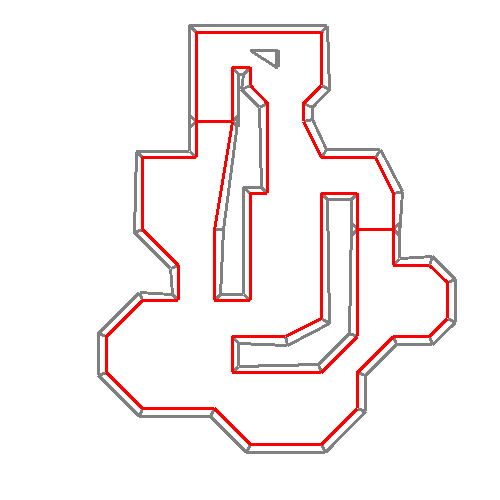
If you were to draw a line inside the shape, following the path, that line would never reconnect to itself. That is the idea.
However the triangulation would still get confused, because it works by removing points as options as it goes. Since it had already hit those points, regardless that they were shared points, it considered them done and wouldn’t properly fill out the shapes in those areas. To get around this I found duplicate points, and slightly moved one pair up by a very small value like 0.1. Then, it wouldn’t consider them the same points because of the 0.1 difference, after the triangulation was completed, I moved the points back down.
Next I had to define rules for what triangles were allowed and disallowed. I went through some trouble for a while getting this to work correctly. But eventually I was able to find all the scenarios I needed. First I check the 2D cross product (also know as the wedge product apparently?) this was a strange one to find information on. But I found that, and checked if its value was proper to determine if the current evaluating vertex was an interior one or not.
Then I checked every single other point versus our current triangle, and if any were inside the triangle we were making, it was no good. If it passed those, we were good to create the triangle. We did this until we couldn’t make triangles any longer.
Now here is a fun GIF of the process, I often used these for debugging purposes. This shows the triangles as it attempts to find valid positions. The light blue triangle is the current one its testing, the blue dot is the current vertex we’re basing everything on, while the red and green dots represent the positions in the list before it (red) and after it (green).
This entire method is still not ideal for this scenario unfortunately. It took me a while to get this to work perfectly, and it is able to create all the triangles for pretty much any scenario of shapes, the shapes it makes aren’t ideal. I did attempt to help fix this by going through a combining pass, where I test triangles next to each other, see if they’re valid, and if so I turn them into one single polygon. You can see that process here, where blue and green highlights are the current shapes being evaluated, and a red shape is the resulting finished combined polygon.
While this definitely improves it, for most developers in CS:GO this isn’t great to work with. Flat rectangles and easier shapes are much better, but this entire method can great long weird shapes. Unfortunately this is the best I have at the time of writing, but I would like to explore better methods in the future.
From Image to CS:GO Map
Moving on, this was one of the most difficult aspects I’ve had to deal with, and while it works fairly well still isn’t perfect (noticing a theme?).
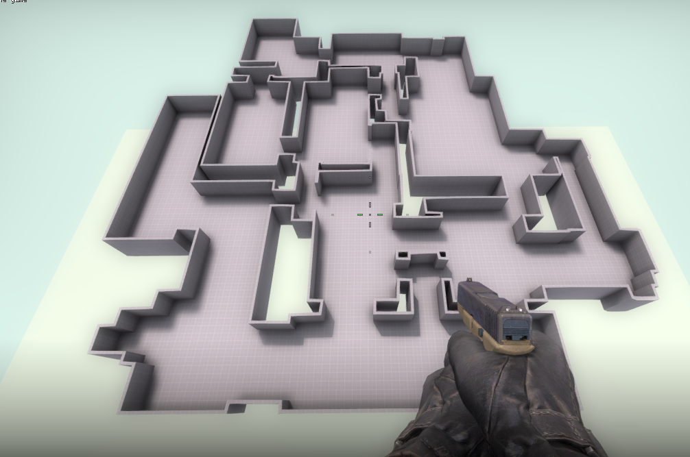
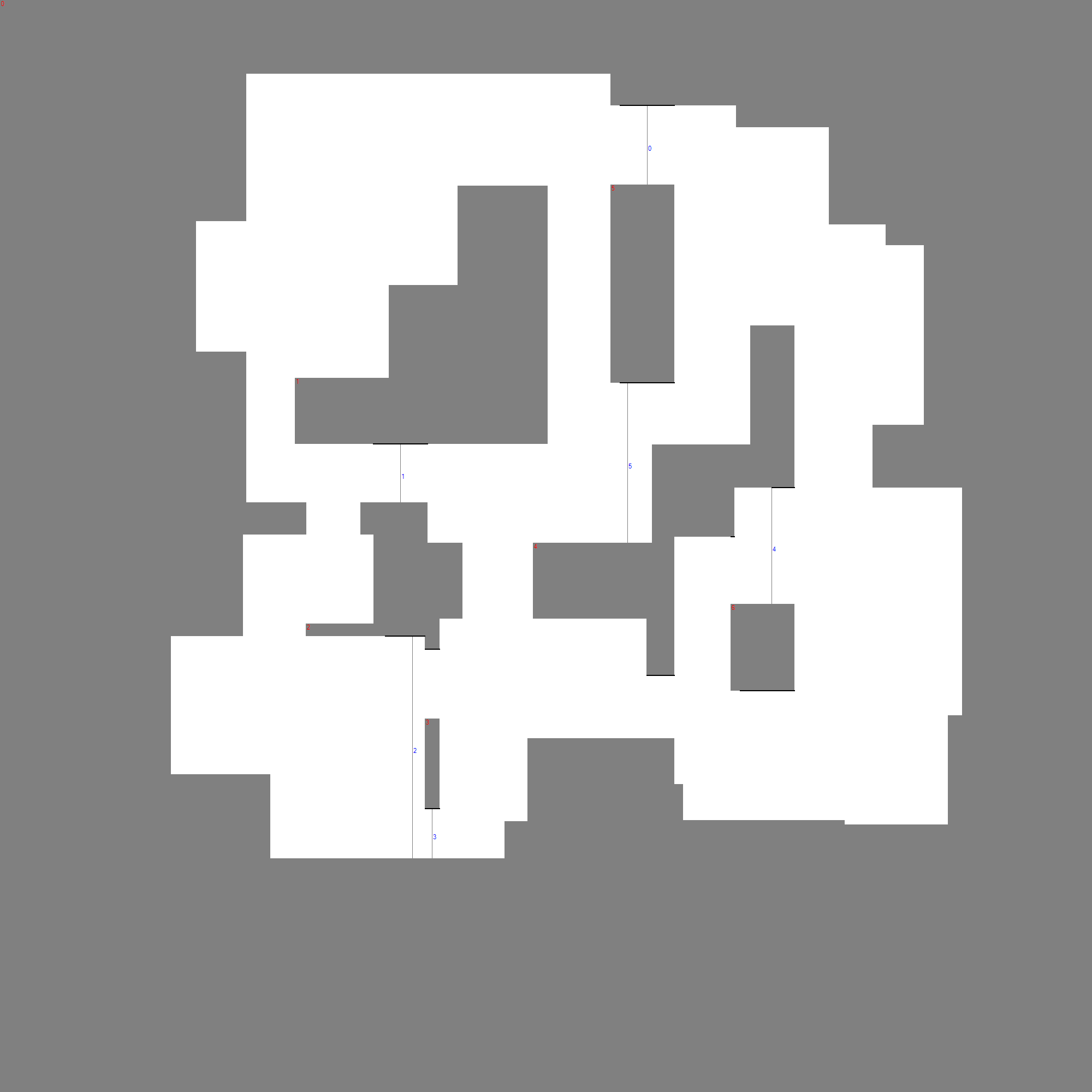
So we’re all on the same page, here’s an example of the end product. It changes this black and white image, into this full map.
I wanted to be able to create an image, at least for the moment in black and white, and have it create brushes out of this. This turned out to be so much more difficult than I anticipated. Again with the triangulation, I won’t be going through my original process, as I’ve gone through so many iterations of this that I can’t remember the timeline.
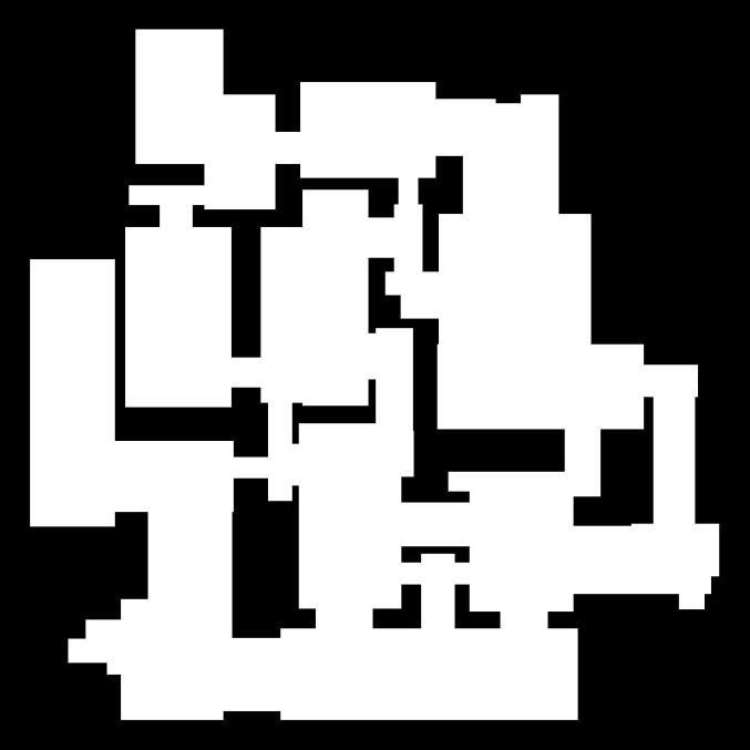
So to begin I load the image into a Bitmap, and from there I’m able to put that into a grid of 1s or 0s based on if the color is greater than a certain value. This is trivial, but there are a few pieces to this. Going back to what I mentioned above, regarding sides touching and looping shapes? That became a large issue here. Even after getting it to generate a shape, if I wanted to have a map that was interconnected, it was very hard. What I ended up doing is detecting any lines that are only a pixel thick, and using that as a guide to tell where those “connections” should be. But even despite that, I would have to add those manually to every single image, and that really sucked.
So after a long time of iterating and testing and writing and doing MATH I finally got a fairly stable solution. I add those thin black lines automatically through a long process. First I go through and detect all the empty (black) space. I use the flood fill algorithm to do this, and I put it into a List<List<Point>> in order to have every single pixel of black, for each chunk.
From there I only get the bottom edges, as that’s all we need to detect. I simply check if a pixel below this pixel is white, if it is, that means this is an edge and we want to keep that one. Then, I realized that I needed to filter it down further. Since I am attempting to make essentially “one” polygon (as I described earlier), I don’t want any of those bottom edges to be edges where if I made a line straight down, they would hit themselves. This would simply create a closed polygon. So I created a pixel raycast function, and checked if they would hit themselves in this scenario, and got rid of those options. Finally from there, I still had a lot of options, so just to filter it a bit, I found the top 100 closest points (to the other black points directly below them).
We’re getting close now. We have a limited selection of points. The next issue was that the generation really didn’t do well if the black lines were on corners or any sort of sharp turn. It would just freak out and create weird shapes, or wall generation would be broken. So for this I went about trying to detect the most flat area. I went through each pixel, did raycasts to its sides on the inside of the area, and the outside, detecting if it hit the opposite color in order to try and create weights to detect sharp corners.
This took a lot of fiddling and weight adjustments, basing it on the length of the raycast (how far it got before it reached max or hit a shape) and determining how centered the point was. Once this was finally working, I simply edit the original grid and draw the line. The only other trouble here was when it would connect to itself. For example if the very top empty space drew a line to a shape below it, and that shape drew a line down to the same shape below it, because that black space wraps around the entire image, I had to filter that out to make sure it cannot connect, otherwise it would create two separate sides. Here’s another debug image of the output after it created those points.
Once that was all okay, it was time to convert this grid into data we could use. I tried a lot of different things for this, and still haven’t found a perfect solution. I was eventually suggested a specific section of this great library, and was able to modify it to work better than anything I wrote. It isn’t quite as perfect as I’d like. It does create duplicate points at times, and it doesn’t do well at slopes. It often creates a lot of unnecessary points along the slope, making the generation more strange.
I would like to eventually refine this, this is probably the second largest issue I have with the tool. This library gives me bad a set of points, which after a bit of modification to try and normalize some of it, remove redundant points, etc. I create a polygon out of which handles the rest.
In the future I would also like to add height to this, while you could technically do it now (using multiple images and setting them to different heights) id like to do this based on color and such, but I’ve run into more trouble than I thought I would.
Misc Notable Features
We’re nearly at an end to this post, but i figured I will briefly go over some slight notable features. I’ve already gone through the most complex bits, but these are a few things that might be interesting.
For things such as slopes, I tried for a while to get this to work as its own shape, but had a lot of trouble. What I eventually found out was much easier was creating a polygon in the shape of a slope, and then simply rotating it to face upwards. This also essentially lets you create any surface in this same way.
Stairs are a simply generator that creates many stretched cubes (based on your input), then creates a slope using the method I mentioned above with a clipping texture, and then even can create railings using the same method.
The wall generator took a bit of time as well to get perfect. It will create walls around a polygon shape (Note, this is before its split up during triangulation). I go through each side of the polygon, and for the two vertices on each bit of that side, I get the vertex normal and then I use the original points, with the normals to extrude the wall out. This makes most walls a trapezoid shape, which is a bit strange, but it certainly the easiest way to go about this. I also wrote in a way to remove specific walls, this is used automatically for areas where polygons share points, so its one long hallway.
I also added the ability to add func_details, which you simply specify them by an ID on the shape. Same thing for the texture and visgroups, which is specified by a string on the shape. Stairs for example are automatically set to func_details because of the many individual pieces.
Finale
I hope some part of this entry was insightful on the process I went through to create this base. The purpose of the tool it to make it so people can generate VMFs easier, and perhaps use them for something new and interesting. This might be a procedurally generated level, or perhaps using the image generation feature to quickly concept map ideas.
As I said there are several things I’d like to fix and improve on, and I’m open to others contributions as well. The Github is open to pull requests and I look forward to seeing what people do with it. You can find all the code open sourced on the repo: https://github.com/7ark/CSGO-VMF-Generator
Support
Want to ask questions or discuss this more? Please feel free to contact me via email at KoseckCory@gmail.com or message me on discord at 7ark#1120.
If you’re interested in supporting me personally, you can follow me on Twitter or Instagram. If you want to support me financially, I have a Patreon and a Ko-fi.
0 comments on “CS:GO VMF Generator Explained”Add yours →